An Inexpensive CB to 10 Meter Conversion
by
Jerry Coffman, K5JC, Formerly WB5RUA
k5jc@arrl.net
Illustrations and Photos
by
Jani Turkia, K5KI
ham@k5ki.com
How would you like a 4 watt QRP AM transceiver, with multiple channels, for 10 meter AM use? Sure, there are ready-to-go units that only require a credit card number, but is it not more fun to convert a radio from 11 meters to 10 meters, at minimal expense? Such a radio would be great for both mobile and fixed station use, and capable of world-wide contacts. How much would such a conversion cost, if you had a suitable radio for conversion? Would you believe not a cent? How do you convert a very common CB radio for use on the 10 meter AM frequencies with excellent performance, with a minimal investment? Let me explain.
Back in the late 1970's and early 1980's, there were several articles in ham magazines about converting various CB radios to 10 meters. The Cybernet board based radios, with the PLL02A phase-locked loop circuit and the three crystals, used in many different brand radios, were especially popular to convert, by changing from an 11.8066 MHz crystal to a crystal of the proper frequency that would move the frequency coverage to ten meters, and then retuning. Midland, Kraco, J.C. Penney, and many other manufacturers used these boards.
H. Knickerbocker1 and Bob Heil2,3 gave good explanations of steps necessary to convert these to ten meter FM. The 11.8066 MHz crystal was replaced with one close to 12.571 MHz, the radio was retuned, AM modulation was disabled, FM modulation added, and optionally an FM detector was added. I converted several radios at the time using these methods, with a few minor variations. Recently, I decided to try my hand at it again. I would encourage studying their articles, before attempting a similar radio conversion.
While these radios are relatively easy to find, at hamfests and on the internet auction sites, the price for the needed crystal was often more than the radio. There had to be a way to convert CB radios to ten meters with a minimal amount of new parts. I had purchased some radios, in great condition, for less than $10 each. Crystals tend to be much more than that.
With each radio, the first step is to make sure it works on it's intended frequencies, before attempting any conversion. If it will not work on 11 meters, it will not work on 10 meters. Your radio may have been modified by a previous owner, so some repair work may be required.
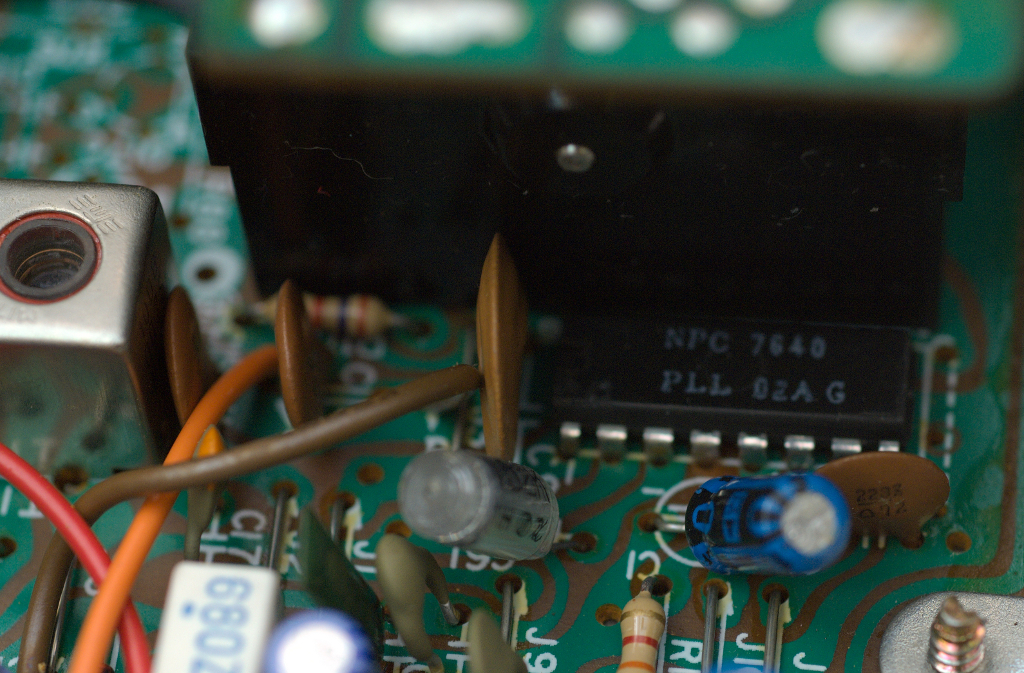
In acquiring radios for my experimentation, I soon discovered there were very similar radios to the three crystal, PLL02A PLL based ones I was looking for, but these radios had only two crystals, without a 11.8066 MHz crystal to be changed! The PLL02A was still there, but no suitable crystal to change. So, how do you move a radio up about 2 MHz in frequency when you do not have a crystal to change? To begin, I downloaded a copy of the service manual5 from www.cbtricks.com for the Hygain 2702 model radio, which was a typical PLL02A PLL radio, with only the 10.240 and 10.695 MHz crystals.
These radios use the various pins on the PLL02A to apply or remove 5 VDC to change frequency, using the channel selector switch. By modifying connections directly to the PLL02A, the frequency produced can be changed. Pin P0 adds/subtracts 10 KHz; P1 20 KHz; P2 40 KHz; P3 80 KHz; P4 160 KHz; P5 320 KHz; and P6 640 KHz. P7 was hardwired to always have 0 VDC and P8 always had 5 VDC applied to it. In studying the PLL02A specifications 6 shown in Table 2, I discovered P7 should add/subtract 1.28 MHz and P8 should add/subtract 2.56 MHz. In these 2 crystal radios, if a pin has 5 VDC, it does not add frequency; if has 0 VDC, it adds frequency. Note that this is the opposite of the 3 crystal boards, with the 11.8066 MHz crystal.
Table A from the service manual shows the binary chart for the various channels, as wired to the channel switch. A little work with the voltmeter showed P7 is always 1 (0 VDC) and P8 is always 0 (5 VDC) . Assuming I could get the VCO to work at the higher frequencies, by removing 5 VDC from pin P8, I could raise the frequency of the radio from 26.965-27.405 MHz to 29.525-29.965 MHz. Now, that would be a great start, just a little high in frequency!
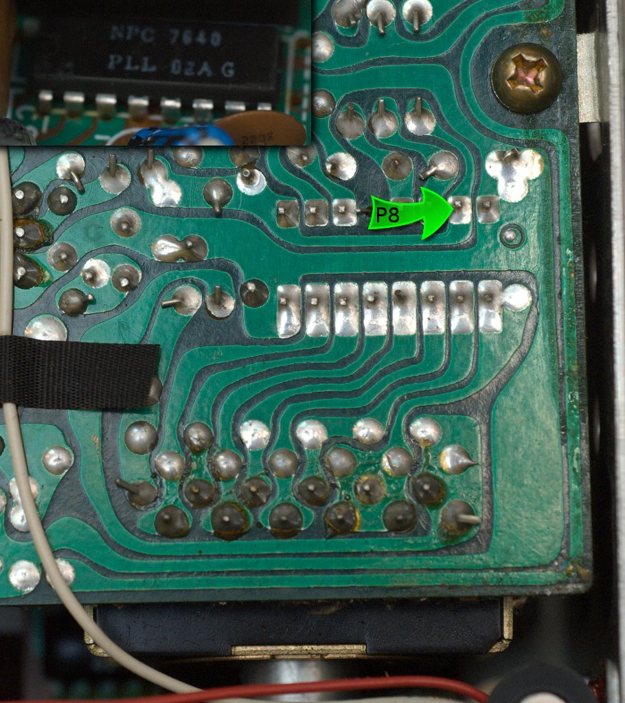
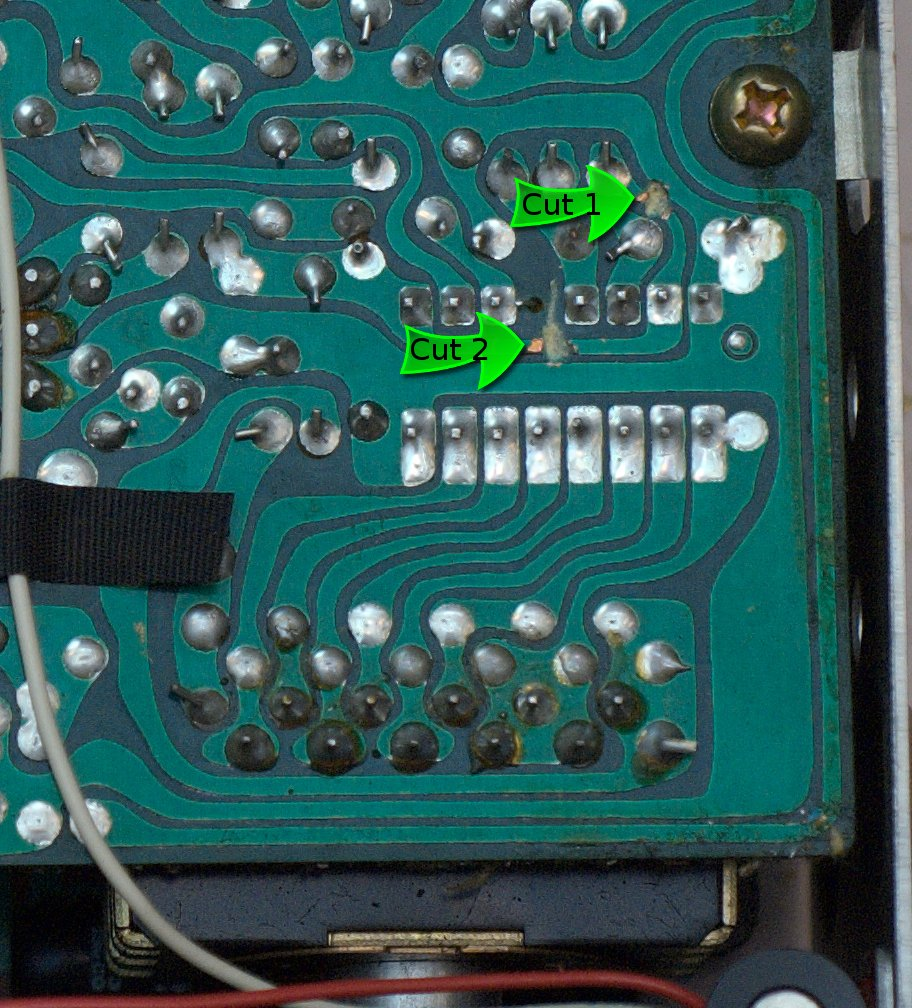
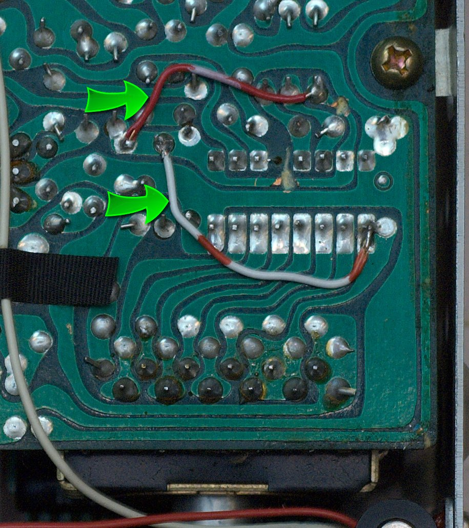
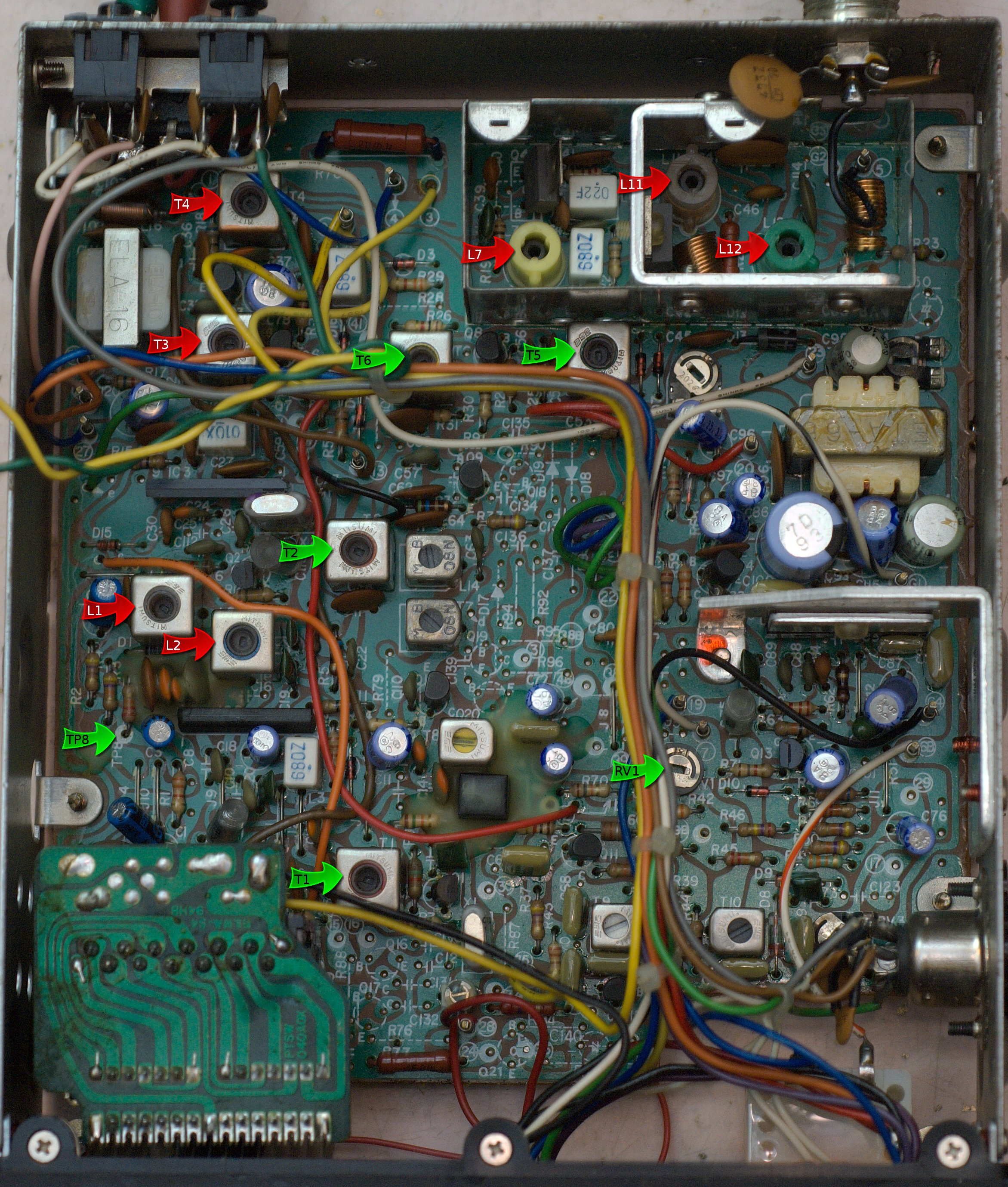
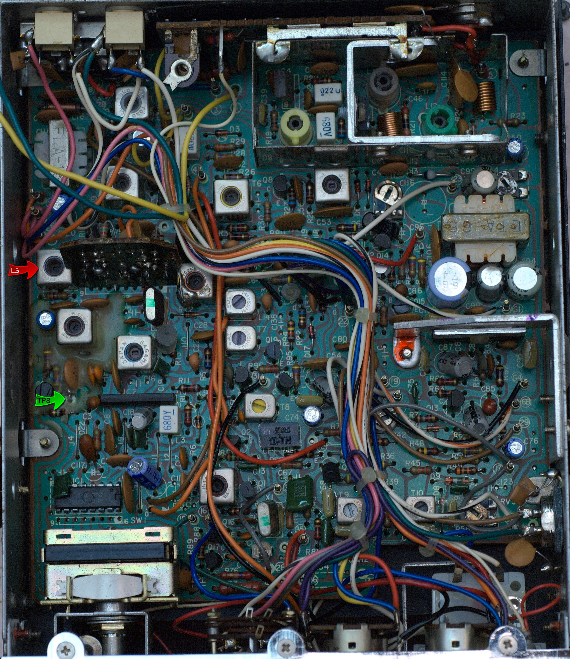
I located P8 on underside of the circuit board and quickly cut the traces on both sides. A short jumper was soldered around pin P8. Now, would it work, or do I now have another radio for the parts box? First step is to adjust the VCO voltage. TP8, located near L1, and ground would have to be between 1.5-3.6 volts, on all channels. Note: Do not use chassis ground, use the -13.6 VDC connection. And be sure to use the proper adjustment tool, as the ferrite slugs break easily. Slowly adjust the slug in L1, while monitoring the voltage on TP8 for about 2 volts. Turning the slug clockwise, brought the voltage down to 2 volts when on channel 1!
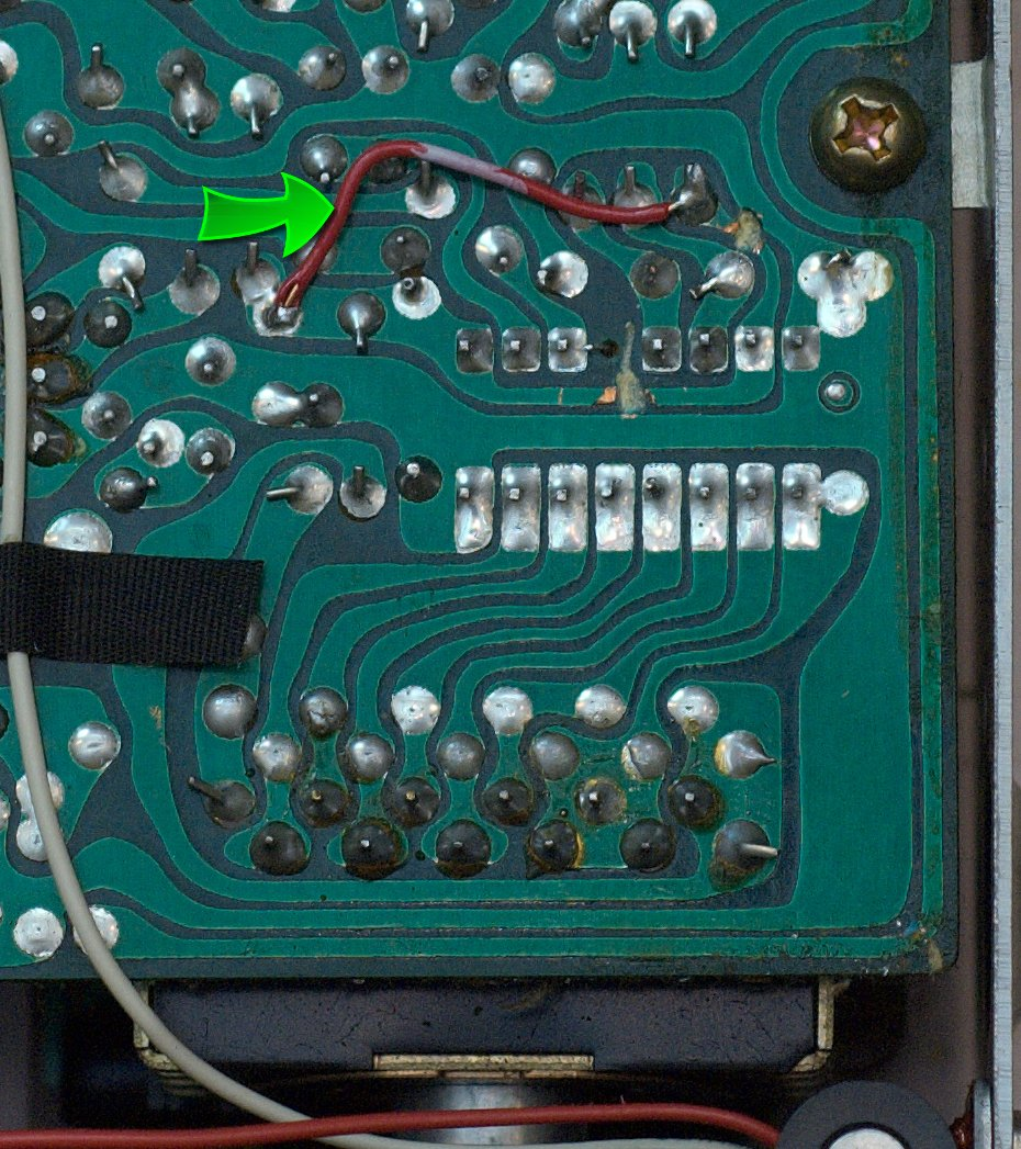
In studying Table A in the service manual, channels 10-38 could be lowered in frequency by 640 KHz by hardwiring +5 VDC to pin P6. Channels 1-9 already have +5 VDC on this pin. This would have channel 10 on 28.995 MHz and channel 40 on 29.325 MHz, covering the 10 meter AM band perfectly! So soldering a wire on the circuit board from the area where pin P8 had gotten +5 VDC to the connection P6, should put the radio into the 10 meter AM band. This little jumper was soon in place.
In theory, channel 1-9 should go from 29.525-29.625 MHz, part of the 10 meter FM band, 5 KHz off frequency, and channels 10-40 should go from 28.995-29.325 MHz, covering the 10 meter AM band. These channels and frequencies are shown in Table 1. I checked the VCO voltage and adjusted L1 so TP8 varied from 1.5-4 VDC on all channels. Note: if the VCO will not lock, get it working before going any further. Now for the receiver and transmitter adjustments.
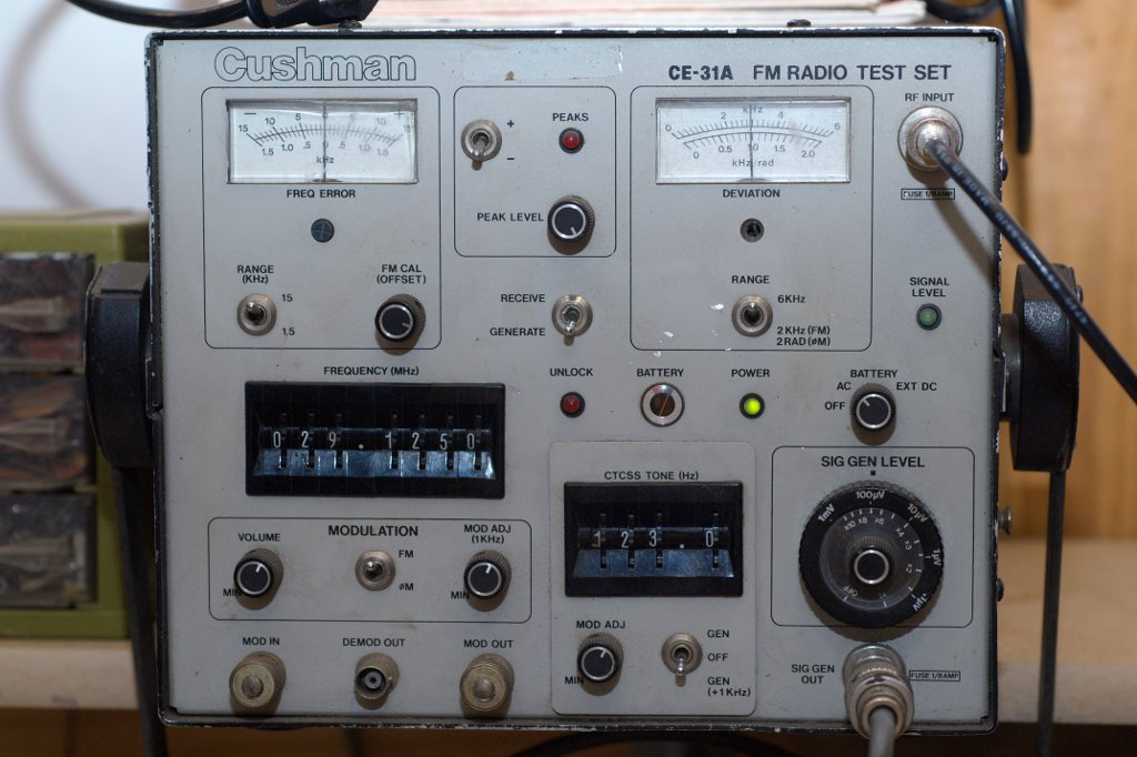
These are the steps I followed: Set the handy service monitor or signal generator to 29.125 MHz. Set the channel selector to channel 20, and open the squelch. Increase the signal, until it can be heard in the radio's speaker. Standard adjustment procedures were used: decrease signal strength as the signal becomes too strong, as adjustments are made. T1, T2, T6, and T5 were adjusted, in that order. How did it work? Less than 1 uv sensitivity! In fact, 0.5 uv or less. Now would be a good time to adjust the squelch sensitivity, too. Adjust RV1 until the squelch opens with a weak, but usable signal.
Hooking up an antenna, and running through the channels revealed channel 8 receiving the 29.620 MHz 10 meter FM repeater from NY! 29.615 MHz, on channel 8, was close enough to 29.620 MHz to receive it, using slope detection. This was a nice side benefit. You may also monitor the 10 meter FM National Simplex frequency, 29.600 MHz, on channel 7, 29.595 MHz.
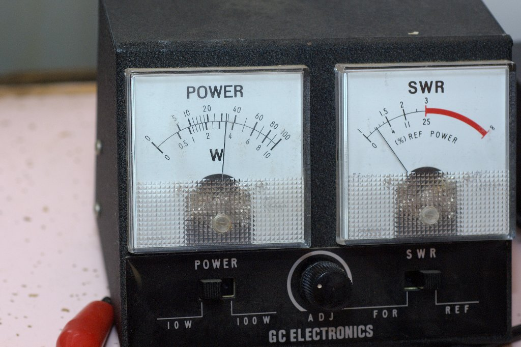
Now for the transmitter. Hook the radio up to a power meter and a dummy load. You will not have any output power, yet. Set the radio to channel 20 and tune a receiver across the room to 29.125 MHz and adjust the volume so you can hear it at the radio. A large S-meter on the receiver is helpful, also.
Adjustments L5, T3 and T4 are critical here, as they form a filter, to only let a narrow band of frequencies through to the final amplifier. As you key the transmitter, you should hear the transmitted signal. If not, either move the receiver closer, or use a better antenna. Slowly adjust L2, listening for a change in tone on the receiver across the room and watching for the S-meter increase. Unkey the transmitter between adjustments. If you do not notice an improvement, move the slug back to where it originally started. You may need to use only a short wire for an antenna on the receiver, as you will overload it, if not careful. Again key the transmitter and adjust L5 slowly, listening carefully. About 1/4 turn clockwise should be close. Then move to T3. Slowly adjust the slug clockwise, listening for a stronger signal in the receiver, and watching the power meter for any movement. Again about 1/4 -1/2 turn should be all that is required. No power output may be obvious on the power meter yet, but you might already see some power output. T4 is next. Only about a 1/4 turn is all that should be required.
As you adjust T4 clockwise, at some point, the power meter should show measurable power. If not, go back to L5, T3, and T4 and tune slightly until you have measurable output and adjust for maximum signal output, as measured on the power meter. These filter adjustments are quite narrow and may require readjustment. Then repeak L2, L5, T3, and T4 for maximum power output.
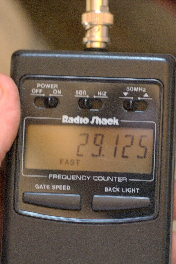
Now for the PA adjustments. Adjust L7, L11 and L12 for maximum output, in that order. They should tune counterclockwise. Power output should now be about 4 watts. Use your frequency counter and verify that the radio is transmitting on 29.125 MHz and not elsewhere. Check for output and frequency on channels 10-38. If power drops off on some channels, you may want to adjust L2, L5, T3 and T4, until power output is uniform from 28.995-29.325 MHz, channels 10-40. Low output on channels 1-9 is not a real problem, since you do not want to transmit AM on the FM portion of the band, anyway.
I hooked the radio up to an outside antenna and heard an AM QSO on channel 11, 29.005 MHz. I waited until he signed with another station and gave him a quick call. It was a W4 in North Carolina. He heard me and came back, after he tuned me in slightly on his vintage Johnson AM transceiver and said I was on 29.005 MHz. He had been closer to 29.000 MHz in frequency, but still heard me. I explained my radio and received good reports from him on the audio. Four watts reached from Arkansas to North Carolina, using a converted CB radio.
The conversion was now complete. A CB to 10 meter AM radio conversion was accomplished with minimal expense. Total additional parts used was a short wire! After putting the covers back on the radio, I printed out a channel chart and taped it to the top of the radio. A frequency counter verified my channel numbers and frequencies.
Ten meters is a great band, but one with too few AM stations from 29.0 to about 29.2 MHz. When the band opens, you can reach thousands of miles with low power and modest antennas. With a conversion like this, it is very inexpensive to have radios for this portion of the band. Plus, they are a lot of fun, both to convert and to use.
Let's start looking for a suitable radio and break out the solder iron. A quick search of the internet showed several radios use this board. A Google search revealed page 91 of "Screwdriver Experts Guide to Peaking Out and Repairing CB Radios" by Lou Franklin4 lists several late 2-crystal AM CB radios using the PLL02A PLL chip. If you find a radio with a PLL02A chip, and only two crystals, 10.240 MHz and 10.695 MHz, it is probably a candidate for this conversion.
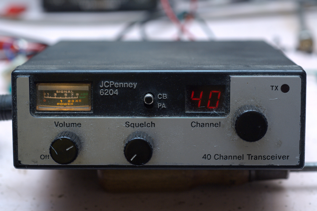
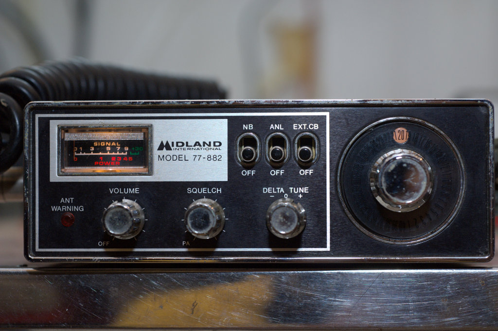
The circuit board used by all these radios is essentially the same, and suitable for conversion to 10 meters. Some radios have more options than others, but they use the same basic circuit board, with the major components in the same locations. On some models, L5 was not there, but the other adjustments were the same. I have converted models Midland 77-857, Kraco KCB4020, J.C. Penney 981-6204 and several others, using the techniques I have described. On some of the radios, instead of cutting the two traces on the circuit board on each side of P8, then soldered a jumper across where P8 used to be connected, I isolated it by clipping the P8 pin on the PLL02A, Either way works fine.
These techniques have been shown to work on several radios, but the normal disclaimer applies. So don't blame me if you break your radio. The proper equipment and experience in tuning radios are helpful. The service manual has detailed tuning instructions, should you need them.
I have enjoyed converting radios to 10 meter AM and probably now have more radios than I will ever use. If some ham wants to try 10 meter AM QRP, contact the author directly if interested in a converted radio. See you on 10 meters!
Table 1. Channels and Frequencies
1 29.525 MHz
2 29.535 MHz
3 29.545 MHz
4 29.565 MHz
5 29.575 MHz
6 29.585 MHz
7 29.595 MHz
8 29.615 MHz
9 29.625 MHz
10 28.995 MHz
11 29.005 MHz
12 29.025 MHz
13 29.035 MHz
14 29.045 MHz
15 29.055 MHz
16 29.075 MHz
17 29.085 MHz
18 29.095 MHz
19 29.105 MHz
20 29.125 MHz
21 29.135 MHz
22 29.145 MHz
24 29.155 MHz
25 29.165 MHz
23 29.175 MHz
26 29.185 MHz
27 29.195 MHz
28 29.205 MHz
29 29.215 MHz
30 29.225 MHz
31 29.235 MHz
32 29.245 MHz
33 29.255 MHz
34 29.265 MHz
35 29.275 MHz
36 29.285 MHz
37 29.295 MHz
38 29.305 MHz
39 29.315 MHz
40 29.325 MHz
Table 2. PLL02A Pin Connections
1 VDD (Positive Power Supply)
2 F in
3 RI
4 FS
5 PD
6 LD
7 P8 (2.56 MHz)
8 P7 (1.28 MHz)
9 P6 (0.64 MHz)
10 P5 (0.32 MHz)
11 P4 (0.16 MHz)
12 P3 (0.08 MHz)
13 P2 (0.04 MHz)
14 P1 (0.02 MHz)
15 P0 (0.01 MHz)
16 VSS (ground)
Notes:
- H. Knickerbocker, A. Weise and R. Stielau, "CB-to-10 FM Best Conversion Yet?" 73, January 1980, p. 117.
- B. Heil, "The 10 Meter FM Handbook", (Marissa, IL: MELCO Publishing, 1980).
- B. Heil, "Experience 10-Meter FM Operation!", QST, August 1981, p. 22.
- L. Franklin, "Screwdriver Experts Guide to Peaking Out and Repairing CB Radios", (Phoenix, AZ: CBC International, 2005), p. 91.
- "Hy-Gain II and III Models 2702 and 2703 Citizens Two-Way Radio 40 channel Mobile" Service Manual, (Hy-Gain de Puerto Rico, Inc, 1977).
- "PLL02A", (http://malzev.tripod.com/comp/pll02a.htm).